
Product overview
S-type pump is to replace SH type single-stage double suction, horizontal split centrifugal pump, which is used to transport clean water and liquid with physical and chemical properties similar to water (the higher temperature of liquid does not exceed 80 ℃). It is suitable for water supply and drainage of factories, mines, cities, power stations, farmland drainage irrigation and various water conservancy projects. According to the requirements of the pump, such as SF, SM and so on.
Model meaning

Performance range
Flow rate: 160 ~ 18000m3 / S
Lift: 12 ~ 125m
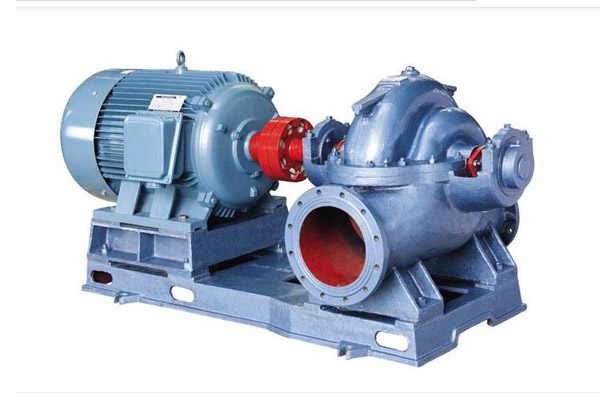
Structural features
S. The suction inlet and outlet of SM, SF and sy pumps are under the axis line of the water pump, perpendicular to the axis and in a horizontal direction. The pump shell is opened in the middle. There is no need to remove the water inlet and discharge pipes and the motor (or other motors) during maintenance. From the direction of the drive end to the pump, the water pump rotates clockwise, and the production can also rotate in the counter clockwise direction according to the needs. It should be specially proposed when ordering.
S. The main parts of SM, SF and sy pumps are: pump body, pump cover, impeller, shaft, double suction sealing ring, shaft sleeve, bearing, etc.
3. After static balance verification, the impeller is fixed by shaft sleeve and sleeve nut on both sides, and its axial position can be adjusted by sleeve nut. The axial force of the impeller is balanced by the symmetrical arrangement of its blades, and the residual axial force is borne by the bearing at the shaft end.
The pump shaft is supported by two single row radial ball bearings or four radial thrust ball bearings. The bearings are installed in the bearing bodies at both ends of the pump body and lubricated with grease or thin oil.
The pump is directly driven by the motor through the elastic sleeve pin coupling.
The shaft seal is a soft packing seal. In order to cool and lubricate the sealing cavity and prevent air from entering the pump, a packing ring is installed between the fillers. When the water pump works, a small amount of high-pressure water flows into the packing chamber through the trapezoidal groove on the open surface of the pump cover or the external unsealed pipe parts to play the role of water seal.
model | flow Q (m3/h) | lift H (m) | speed n (r/min) | power P(kw) | efficiency n (%) | NPSH (NPSH)r(m) | |
Shaft power | Motor power | ||||||
100S90 | 80 | 90 | 2950 | 30.1 | 37 | 65 | 2.5 |
100S90A | 72 | 75 | 2950 | 23 | 30 | 64 | 2.5 |
150S100 | 160 | 100 | 2950 | 59.8 | 75 | 73 | 3.5 |
150S78 | 160 | 78 | 2950 | 45 | 55 | 75.5 | 3.7 |
150S78A | 144 | 62 | 2950 | 33.4 | 45 | 72.6 | 3.7 |
150S50 | 160 | 50 | 2950 | 27.3 | 37 | 80.4 | 3.9 |
150S50A | 144 | 40 | 2950 | 20.0 | 30 | 75.5 | 3.9 |
150S50B | 133 | 36 | 2950 | 18.0 | 22 | 72.5 | 3.9 |
200S95 | 280 | 95 | 2950 | 91.4 | 132 | 79.2 | 5.3 |
200S95A | 270 | 85 | 2950 | 83.3 | 110 | 75 | 5.3 |
200S95B | 260 | 75 | 2950 | 73.8 | 90 | 72 | 5.3 |
200S63 | 280 | 63 | 2950 | 58.3 | 75 | 82.7 | 5.8 |
200S63A | 270 | 46 | 2950 | 45.1 | 55 | 75 | 5.8 |
200S42 | 280 | 42 | 2950 | 38.1 | 45 | 84.2 | 6 |
200S42A | 270 | 36 | 2950 | 33.1 | 37 | 80 | 6 |
250S65 | 485 | 65 | 1450 | 109.2 | 132 | 78.6 | 3.1 |
250S65A | 420 | 48 | 1450 | 88.5 | 90 | 77.7 | 3.1 |
250S39 | 485 | 39 | 1450 | 61.5 | 75 | 83.6 | 3.2 |
250S39A | 468 | 30 | 1450 | 48.4 | 55 | 79 | 3.2 |
250S24 | 485 | 24 | 1450 | 36.9 | 45 | 85.8 | 3.5 |
250S24A | 414 | 20 | 1450 | 27.2 | 37 | 83.3 | 3.5 |
250S14 | 485 | 14 | 1450 | 21.5 | 30 | 85.8 | 3.8 |
250S14A | 432 | 11 | 1450 | 15.2 | 18.5 | 82.7 | 3.8 |
300S90 | 790 | 90 | 1450 | 243 | 320 | 79.6 | 4.2 |
型號 | 流量Q (m3/h) | 揚程H (m) | 轉速n (r/min) | 功率P(kw) | 效率n (%) | 汽蝕余量 (NPSH)r(m) | |
軸功率 | 電機功率 | ||||||
300S90A | 756 | 78 | 1450 | 216.4 | 280 | 74.2 | 4.2 |
300S90B | 720 | 67 | 1450 | 180 | 220 | 73 | 4.2 |
300S58 | 790 | 58 | 1450 | 147.9 | 200 | 84.2 | 4.4 |
300S58A | 720 | 49 | 1450 | 118.0 | 160 | 82.5 | 4.4 |
300S58B | 684 | 43 | 1450 | 100 | 132 | 80 | 4.4 |
300S32 | 790 | 32 | 1450 | 79 | 90 | 86.8 | 4.6 |
300S32A | 720 | 26 | 1450 | 60.7 | 75 | 84 | 4.6 |
300S19 | 790 | 19 | 1450 | 47.1 | 55 | 86.8 | 5.2 |
300S19A | 720 | 16 | 1450 | 39.2 | 45 | 80 | 5.2 |
300S12 | 790 | 12 | 1450 | 30.4 | 37 | 84.8 | 5.5 |
300S12A | 684 | 10 | 1450 | 23.9 | 30 | 78.4 | 5.5 |
350S125 | 1260 | 125 | 1450 | 533 | 680 | 80.5 | 5.4 |
350S125A | 1181 | 112 | 1450 | 461 | 570 | 78.2 | 5.4 |
350S125B | 1098 | 96 | 1450 | 373 | 500 | 77 | 5.4 |
350S75 | 1260 | 75 | 1450 | 303 | 360 | 85.2 | 5.8 |
350S75A | 1170 | 65 | 1450 | 244.4 | 280 | 84.2 | 5.8 |
350S75B | 1080 | 55 | 1450 | 196.3 | 220 | 82.4 | 5.8 |
350S44 | 1260 | 44 | 1450 | 172.5 | 220 | 87.5 | 6.3 |
350S44A | 1116 | 36 | 1450 | 129.5 | 160 | 84.5 | 6.3 |
350S26 | 1260 | 26 | 1450 | 102 | 132 | 87.5 | 6.7 |
350S26A | 1116 | 21 | 1450 | 76.9 | 90 | 83.4 | 6.7 |
350S16 | 1260 | 16 | 1450 | 64.4 | 75 | 85.4 | 7.1 |
350S16A | 1044 | 13 | 1450 | 47 | 55 | 78.3 | 7.1 |
400S90 | 1620 | 90 | 1450 | 473 | 560 | 84 | 6.2 |
400S90A | 1460 | 73 | 1450 | 345 | 450 | 84 | 6.2 |
型號 | 流量Q (m3/h) | 揚程H (m) | 轉速n (r/min) | 功率P(kw) | 效率n (%) | 汽蝕余量 (NPSH)r(m) | |
軸功率 | 電機功率 | ||||||
400S90B | 1300 | 58 | 1450 | 245 | 315 | 84 | 6.2 |
400S40 | 1080 | 40 | 970 | 140 | 185 | 85 | 5.1 |
400S40A | 1007 | 33 | 970 | 107 | 160 | 84.5 | 5.1 |
400S40B | 870 | 26 | 970 | 73.3 | 110 | 84 | 5.1 |
500S98 | 2020 | 98 | 970 | 678.1 | 800 | 79.5 | 4.1 |
500S98A | 1872 | 83 | 970 | 539 | 630 | 78.5 | 4.1 |
500S98B | 1746 | 74 | 970 | 450.1 | 560 | 78.7 | 4.1 |
500S59 | 2020 | 59 | 970 | 388.2 | 450 | 83.6 | 4.5 |
500S59A | 1872 | 49 | 970 | 332.32 | 400 | 75.6 | 4.5 |
500S59B | 1746 | 40 | 970 | 255.8 | 315 | 74 | 4.5 |
500S35 | 2020 | 35 | 970 | 218.2 | 280 | 83.6 | 4.8 |
500S35A | 1746 | 27 | 970 | 150.6 | 220 | 75.6 | 4.8 |
500S22 | 2020 | 22 | 970 | 143.6 | 185 | 74 | 5.2 |
500S22A | 1746 | 17 | 970 | 100.6 | 132 | 88.2 | 5.2 |
500S13 | 2020 | 13 | 970 | 85.7 | 110 | 85.2 | 5.7 |
600S22 | 3170 | 22 | 970 | 215.8 | 250 | 84.2 | 7 |
600S22A | 2860 | 18 | 970 | 161.1 | 185 | 80.3 | 7 |
600S32 | 3170 | 32 | 970 | 310.4 | 355 | 83.4 | 7 |
600S32A | 2850 | 26 | 970 | 229 | 280 | 88 | 7 |
600S47 | 3170 | 47 | 970 | 456 | 560 | 87 | 6.5 |
600S47A | 2920 | 40 | 970 | 361 | 450 | 89 | 6.5 |
600S75 | 3170 | 75 | 970 | 736 | 900 | 88 | 6 |
600S75A | 2920 | 65 | 970 | 600.2 | 710 | 89 | 6 |
600S75B | 3170 | 55 | 970 | 477.5 | 560 | 88 | 6 |
600S100 | 2950 | 100 | 970 | 1015.6 | 1250 | 87 | 6 |
型號 | 流量Q (m3/h) | 揚程H (m) | 轉速n (r/min) | 功率P(kw) | 效率n (%) | 汽蝕余量 (NPSH)r(m) | |
軸功率 | 電機功率 | ||||||
600S100A | 2710 | 90 | 970 | 875.4 | 1120 | 85 | 6 |
600S100B | 3170 | 80 | 970 | 751.9 | 900 | 85 | 6 |
800S22 | 3000 | 22 | 730 | 370.2 | 450 | 84 | 7 |
800S22 | 2830 | 14 | 585 | 190.6 | 250 | 82 | 5 |
800S22A | 5500 | 17 | 730 | 254.1 | 315 | 89 | 7 |
800S22A | 4400 | 11 | 585 | 133.3 | 185 | 88 | 5 |
800S32 | 4830 | 32 | 730 | 538.5 | 630 | 87 | 74.5 |
800S32 | 3870 | 20 | 585 | 272.3 | 315 | 89 | 7 |
800S32A | 5500 | 26 | 730 | 389 | 450 | 88 | 4.5 |
800S32A | 3960 | 17 | 585 | 210.7 | 250 | 88 | 6.5 |
800S47 | 5500 | 47 | 730 | 782.2 | 1000 | 87 | 4.2 |
800S47 | 4400 | 30 | 585 | 403.9 | 450 | 90 | 6.5 |
800S47A | 5070 | 40 | 730 | 621 | 710 | 89 | 4.2 |
800S47A | 4060 | 25 | 585 | 314.1 | 355 | 89 | 6 |
800S76 | 5500 | 76 | 730 | 1293.6 | 1600 | 88 | 4.2 |
800S76 | 4400 | 49 | 585 | 674.9 | 800 | 88 | 6 |
800S76A | 5080 | 65 | 730 | 1034 | 1250 | 87 | 6 |
800S76A | 4070 | 42 | 585 | 541 | 630 | 86 | 4.2 |
800S76B | 4680 | 55 | 730 | 824.7 | 1000 | 85 | 6 |
800S76B | 3750 | 35 | 585 | 425.5 | 500 | 84 | 4 |
It is suitable for factories, mines, urban water supply, power stations, farmland irrigation and various water conservancy projects.
Assembly, disassembly, installation and disassembly:
Assembly of rotor parts: successively install impeller, shaft sleeve, shaft sleeve nut, packing sleeve, packing ring, packing gland, water retaining ring and bearing parts on pump shaft, and sleeve double suction sealing ring, and then install coupling.
Install the rotor parts on the pump body, adjust the axial position halo of the impeller to the middle of the double suction sealing rings on both sides, and fasten the bearing body cover with the fixed screws.
Install the packing, put the paper pad in the middle face, cover the pump cover, tighten the nut of the pump cover after tightening the stud pin, and finally install the material cover. However, do not press the packing too tightly. If the packing is too tight, the shaft sleeve will be heated and the power consumption will be large. If the packing is too loose, the liquid leakage will be large and the pump efficiency will be reduced.
After assembly, the pump shaft can be rotated by hand without rubbing, and the rotation is smooth and even. The disassembly can be carried out in reverse order according to the above assembly sequence. install
Check whether the centrifugal pump and motor are damaged.
The installation height of the pump, together with the hydraulic loss of the suction pipe and its speed, shall not be greater than the allowable suction height specified in the sample. The foundation size shall conform to the installation dimension of pump unit.
Installation sequence:
Place the water pump on the concrete foundation with embedded anchor bolts, correct the level by adjusting the wedge-shaped cushion block between them, and properly tighten the anchor bolts to prevent walking.
Pour concrete after the foundation and pump feet.
After the concrete is dry, tighten the anchor bolts and recheck the levelness of the water pump.
Correct the concentricity of motor shaft and water pump shaft. Make the two shafts in a straight line, the concentricity tolerance on the outer circle of the two shafts is 0.1 mm, and the non-uniformity tolerance of the end clearance along the circumference is 0.3 mm (check again after connecting the inlet and outlet water pipes and trial operation, and still meet the above requirements).
After checking that the rotation direction of the motor is consistent with that of the water pump, install the coupling and the connecting pin.
The water inlet and outlet pipes shall be supported by another bracket instead of the pump body.
The junction surface between the water pump and the pipeline should ensure good air tightness, especially for the water inlet pipeline, it must ensure strict air leakage, and there should be no possibility of trapping air on the device.
If the centrifugal pump is installed above the water level, the bottom valve can be installed in order to start the pump. Vacuum water diversion can also be used.
After the water pump and the water outlet pipeline, it is generally necessary to install gate valve and check valve (the lift less than 20 meters can not be used), and the check valve is installed behind the gate valve. The above installation method refers to the pump unit without common base.
Install the pump with a common base and adjust the level of the unit by adjusting the wedge pad between the base and the concrete foundation. Concrete is then poured in between them. The installation principle and requirements are the same as those of units without common base. Start, stop and run
1. Start and stop:
Before starting, rotate the pump rotor, which should be smooth and even.
Close the outlet valve and inject water into the pump (if there is no bottom valve, use vacuum pump to empty water) to ensure that the pump is full of water and no air entrapment.
If the pump is equipped with a vacuum gauge or a pressure gauge, turn off the rotary base connected with the pump, and then start the motor. After the speed is normal, open it again. Then gradually open the outlet gate valve. If the flow is too large, the gate valve can be properly turned down for adjustment; otherwise, if the flow is too small, open the gate valve.
Tighten the compression nut on the packing gland evenly to make the liquid leak out in drops. At the same time, pay attention to the temperature rise at the packing chamber.
When the pump is stopped, first close the cock of vacuum gauge and pressure gauge and the gate valve on the water outlet pipeline, and then turn off the power supply of the motor. If the ambient temperature is low, open the square plug at the bottom of the pump body to remove the water, so as to avoid freezing crack.
When it is not used for a long time, the water pump should be disassembled and the water on the other part should be wiped dry.
2. Operation:
The maximum temperature of water pump bearing should not exceed 75 ° C.
The amount of calcium base grease used for lubricating the bearing should be 1 / 3 ~ 1 / 2 of the bearing body space.
When the packing is worn, the packing gland can be pressed properly. If it is worn too much, it should be replaced.
Check the coupling parts regularly. Pay attention to the temperature rise of motor bearing.
In case of noise or other abnormal sound during operation, stop the machine immediately, check the cause and eliminate it.
If the rated speed of the pump is n, the flow rate is Q, the head is h, the shaft power is n, and the speed is reduced to N1. After the speed reduction, the flow, head and shaft power are Q1, H1 and N1 respectively
Q1=(n1/n)Q H1=(n1/n)2H N1=(n1/n)3N